Embedded Systems Integration Guide
This chapter demonstrates how to integrate generated C code from itemis CREATE on your device and ends up by referring to according examples for each scenario. State machine code generated by itemis CREATE can effectively be used on embedded systems. The integration contains different parts, but can mostly be described in a generic way, as most steps of the integration are platform independent.
The differences of the integration mostly stem from the selected execution semantics - cycle based or event driven - as well as the used functionalities, such as in, out and timed events. Other best practice implementation patterns can be based on whether a bare metal microcontroller or an real-time operating system (RTOS) is used. So, there are different factors which may have an impact on the integration:
In the statechart:
- State Machine execution
- CycleBased
- EventDriven
- Used event types
- In events
- Time events
- Out events
In the environment:
- Bare-metal or RTOS
- Usage of interrupts or polling
- Usage of sleep modes
This guide will give an overview of the most common and well known design patterns for bare metal and RTOS based implementations in a generic way. It additionally provides examples for concrete target platforms like bare-metal Arduino, FreeRTOS, and Zephyr RTOS. It will be continuously expanded.
Polling vs.Interrupts
Programming bare-metal microcontrollers without any kind of RTOS or scheduler mainly leads to the architectural decision: Polling or Interrupts.
This section will give a short overview of how both design patterns work.
Polling
Polling is a simple approach to get a first prototype running. Most programs look like this:
void main() {
	init();
	while(true){
		readInputs();
		doStuff();
		updateOutputs();
		delay_ms(100);
	}
}
The program starts with an initialization. After this, everything will be handled in a while loop, where the inputs will be polled cyclically - in this case every 100 milliseconds plus the execution time the program. Waiting for x milliseconds does not need to be realized in a blocking delay function, it also can be done by using sleep modes and a timer interrupt. But the main idea of polling is cyclic reacting on events.
For applications where events/inputs only rarely occur, this is not a good design choice, as the sensors are read frequently. This will lead to higher power consumption.
Interrupts
Using interrupts is the second approach, where the system reacts on interrupts, which can occur asynchronously. Thus, the system does not need to cyclically poll the inputs. The normal execution of the program will be interrupted and it jumps to the Interrupt Service Routine (ISR), which then will be executed. Typically, the execution of the ISR should be as fast as possible, as other interrupts could occur while executing the ISR. Therefore, bool flags are commonly used, which serve as memory. A simple implementation look like this:
int main() {
	while(true) {
		if(bool_flag1 == true) {
			doStuff();
			bool_flag1 = false;
		}
		if(bool_flag2 == true) {
			doDifferentStuff();
			bool_flag2 = false;
		}
		// sleep_mode();
	}
}

ISR_1 {
	bool_flag1 = true;
}

ISR_2 {
	bool_flag2 = true;
}
Each ISR uses one specific boolean flag, which stores wherever an interrupt has occurred. This pattern is often combined with a sleep mode, so that the microcontroller's CPU is only active after an interrupt. This pattern is often used for low power applications, which are powered by batteries.
Example State Machine for Integration
The complexity of the state machine can increase in a development process. Thus, it's recommended to specify how the API (Application Programming Interface) should be accessed. While the API depends on the execution and used event types, this guide tries to break down the main elements and define an expandable design pattern. Therefore, the following example will be used for all integration guides.
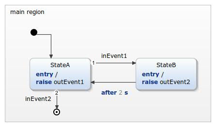
Example State Machine
The state machine contains three types of events: two in events (inEvent1, inEvent2), two out events (outEvent1, outEvent2) and one timed event (after 2 s). Two states are connected with the inEvent1 and the `after 2 s` event. Each state raises one of out event. Additionally, a final state has been added, which also is part of the API. It only can be reached by raising the in event inEvent2, if the state machine's state StateA is active.
These are the main parts of the state machine, which can be used and must be handled:
- raise in events
- raise timed events
- handle out events
- check if the state machine is final
Bare-Metal Integration
This section describes how to integrate a state machine with a cycle based or event driven execution semantic on any microcontroller, so on any embedded device. The integration can be structured in three parts, which results the main part of your program.
- Initialization - called once
- While loop - calling the state machine until it's final
- Final - called if the state machine is final
According to the used State Machine, there are different parts, which must be taken into account:
- In Events
- Timed Events
- Out Events
Main Function
The main function could be realized as following: First, the hardware will be initialized. Then the timers will be taken into account. After this the state machine will be initialized, the out event observers will be initialized and subscribed, and finally the state machine will be entered.
At this point the state machine will be called as long as the state machine is not final. Note: If there is no final state defined the behavior is equal to a while(true) loop. At first all in events will be raised. After this the timer will be updated, which internally raises time events. The behavior is similar to in events. Then the runCycle will be called, which handles the logical execution of the state machine. This is only needed if the execution semantics is cycle-based and must only be executed based on the elapsed time, e.g. 200 ms for a CycleBased(200) state machine. The out events are observed and callbacks are called if the out events are raised, while the state machine is executed. The last step, if wanted, is setting the microcontroller into a sleep mode.
void main() {
	// Initialization

	hardwareInit();

	#ifdef TIME_EVENTS
		timerInit();
	#endif

	statemachine_init();

	#ifdef OUT_EVENTS
		subscribe_observers();
	#endif

	statemachine_enter();

	// While loop
	while(!statemachine_isFinal()) {
		#ifdef IN_EVENTS
			handleInEvents();
		#endif

		#ifdef TIME_EVENTS
			handleTimer();
		#endif

		#ifdef CYCLE_BASED
		if(elapsedTime >= cyclePeriod) {
			elapsedTime = 0;
			statemachine_runCycle();
		}
		#endif

		#ifdef SLEEP_MODE
			goToSleep()
			// wait for Interrupt
		#endif
	}
}
Handle In Events
For now on, there are two different ways of how the events should interact on the embedded system. One design pattern is polling. The other one is the usage of interrupts.
A design using polling cyclically updates the status of the inputs and raises the respective event.
void handleInEvents() {
	if(readGPIO(1)) {
		statemachine_raise_inEvent1();
	}
	if(readGPIO(2)) {
		statemachine_raise_inEvent2();
	}
}
As already described in the Interrupt section, a design using interrupts recommends bool flags as storage for the event.
void handleInEvents() {
	if(inEvent1) {
		statemachine_raise_inEvent1();
		inEvent1 = false;
	}
	if(inEvent2) {
		statemachine_raise_inEvent2(inEvent2Value);
		inEvent2 = false;
	}
}

Sensor1_ISR{
	inEvent1 = true;
}

Sensor2_ISR{
	inEvent2 = true;
	inEvent2Value = readSensor2();
}
Handle Timer
Handling the timer is more comprehensive. Each time event of the state machine must be updated and handled because in detail they are nothing else than an in event. Therefore, a timer service is provided in the examples. This timer service must be updated with the elapsed time since its last call, which leads to the next implementation point: Determining the time.
On a pure bare-metal implementation there is no such thing as elapsed time. Everything depends on cycles.
Imagine a microcontroller running with a clock of 16MHz. Running one instruction needs 1/16MHz = 62.5ns. A delay() function 100000 would need 6,25 ms. A first approach updating the timer could be:
void main() {
	while(true) {
		delay(100000);
		updateTimer(6,25);
		runCycle();
	}
}
But using this implementations has two big drawbacks:
- the delay function is blocking
- the execution time of the updateTimer and runCycle functions are not taken into account
A much more precise design is using timer interrupts, which can generate a periodic interrupt every x cycles:
void handleTimer() {
	if(updateTimerFlag) {
		updateTimer(TIMER_TICK_MS);
		updateTimerFlag = false;
	}
}

#define TIMER_TICK_MS 32 // 32 ms for example
Timer_ISR{
	updateTimerFlag = true;
}
Some microcontrollers, like the Arduino, support functions like millis(), which are in fact using a similar method, but storing the elapsed time since starting the device. This time can be used to determine the elapsed time between two cycles in a loop:
void loop() {
	current_millis = millis();
	updateTimer(current_millis - last_cycle_time);
	statemachine_runCycle();
	last_cycle_time = current_millis;
}
For prototyping, this implementation can be used, but it should be considered that the timer will overflow after approximately 50 days. That's why we highly recommend a implementation with interrupts as described before.
Handle Out Events
Out events raised by the state machine can be checked by using the state machine's API. The default case is using observables, which must be initialized and registered before the state machine is entered. If an out event gets raised, the registered callback of the observer will be called. Thus, out events are handled while executing the state machine's runCycle. They can be used to wire up different actuators. Mapping values, e.g. integers, to the out events is also possible.
void handleOutEvents() {
	if(statemachine_israised_outEvent1()) {
		controlActuator1();
	}
	if(statemachine_israised_outEvent2()) {
		controlActuator2(statemachine_get_outEvent2_value());
	}
}

void on_outEvent1(StateMachine* handle) {
	controlActuator1();
}

void on_outEvent2(StateMachine* handle, sc_integer value) {
	controlActuator2(value);
}

void subscribe_observers(StateMachine *handle, sc_single_subscription_observer *outEvent1Observer, sc_single_subscription_observer_sc_integer *outEvent2Observer) {
	sc_single_subscription_observer_init(outEvent1Observer, handle, (sc_observer_next_fp) on_outEvent1);
	sc_single_subscription_observer_subscribe(outEvent1Observer, &handle->iface.outEvent1);

	sc_single_subscription_observer_sc_integer_init(outEvent2Observer, handle, (sc_observer_next_fp) on_outEvent2);
	sc_single_subscription_observer_sc_integer_subscribe(outEvent2Observer, &handle->iface.outEvent2);
}
Arduino Bare-Metal Integration
There are two examples for a bare-metal integration using interrupts and polling for Arduino and can be used for both execution semantics: CycleBased and EventDriven. They have been tested with an Arduino Uno (ATmega328p) and an Arduino Mega (ATmega2560):
Add them to itemis CREATE with the example wizard:
File -> New -> Example... -> itemis CREATE Statechart Examples -> Embedded Systems Integration Guide -> Arduino - Bare-Metal Interrupts/Polling ©
RTOS Integration
The integration of itemis CREATE with RTOS (Real-Time Operating System) like Zephyr, FreeRTOS, ThreadX (Azure RTOS), or others allows embedded developers to manage state transitions based on real-time events and timer-driven tasks efficiently. By leveraging RTOS tasks or threads, itemis CREATE’s generated code can seamlessly respond to system events and timing requirements.
Note: In the following threads will be used, but it can also be replaced with tasks.
Threads and Queue Flow
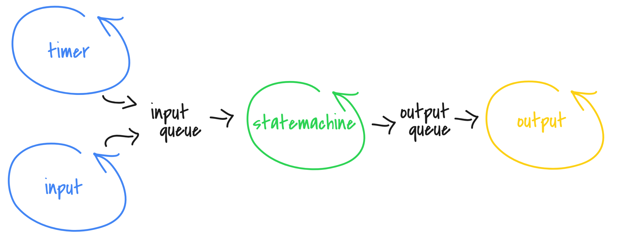
RTOS message queues serve as the bridge between RTOS threads and the state machine, ensuring that events and timer updates are processed efficiently without blocking other system operations. Every participant uses the in event queue to store incoming events that will be raised in the state machine. Outgoing events are pushed into a out event queue, which allows the client to process them spearately. The flow is shown in the image below:
RTOS Queues
The image shows a flowchart representing the integration of RTOS elements with itemis CREATE's state machine. Here’s a description of each component:
- Timer (blue circle): A thread that periodically generates a time event and sends them to the input queue.
- Input (another blue circle): Represents a thread that handles external inputs and also sent the input events to the input queue. An input could be an asynchronous event like a button click.
- Input Queue: This queue collects events from both the timer and input thread.
- State Machine (green circle): The core processing thread, which dispatches the events from the input queue and raising events in the generated state machine code based on the input events.
- Output Queue: Collects output events or actions from the state machine and forwards them to the output thread.
- Output (yellow circle): Represents the thread of processed outputs from the output queue. It handles actions that interact with other systems or provide feedback.
This setup illustrates a structured event-driven architecture where inputs are queued, processed by a state machine, and then sent to an output queue.
Example Code
The Example Code section provides a pseudo-implementation of an RTOS setup that integrates with a state machine. Please refer to the linked examples for concrete implementations for freeRTOS and Zephyr. This setup includes separate threads for managing timers, inputs, outputs and the state machine itself. Here’s a breakdown of each thread's purpose:
Timer Thread
The Timer Thread runs every 100 ms, using a defined interval (TIMER_THREAD_TIME_MS). Within its callback function, it sends a timer event (updateTimerServiceID) to the input queue, which is then processed by the state machine to keep track of timed actions.
#define TIMER_THREAD_TIME_MS 100 // every 100 ms

TimerThread timerThread(timer_thread_callback, TIMER_THREAD_TIME_MS);

void timer_thread_callback()
{
	int event_id = updateTimerServiceID;
	queue_push(&inEventQueue, event_id);
}
Input Thread
The Input Thread continuously monitors for specific events (e.g., event1 and event2). When an event occurs, it pushes the corresponding event ID into the input queue (inEventQueue). This allows the state machine to handle various external inputs as they occur.
Thread input_thread(input_thread_callback);

void input_thread_callback() {
	while (1) {
		if (event1) {
			int event_id = inEvent1ID;
			queue_push(&inEventQueue, eventId);
		}
		if (event2) {
			int event_id = inEvent2ID;
			queue_push(&inEventQueue, eventId);
		}
	}
}
State Machine Thread
The State Machine Thread handles events from the input queue. It retrieves events using queue_pop, and based on the event ID, it either updates the timer service or raises specific events (inEvent1 or inEvent2) in the state machine. This thread allows the state machine to process events sequentially, making it responsive to both time-based and input-triggered events.
Thread statemachine_thread(statemachine_thread_callback, statemachine);

void statemachine_thread_callback(void *arg)
{
	StateMachine *statemachine = (StateMachine *)arg;
	while (1)
	{
		int receivedInEventID = queue_pop(&inEventQueue);
		if (receivedInEventID == updateTimerServiceID)
		{
			sc_timer_service_proceed(&timer_service, TIMER_THREAD_TIME_MS);
		}
		else if (receivedInEventID == inEvent1ID)
		{
			statemachine_raise_inEvent1(&statemachine);
		}
		else if (receivedInEventID == inEvent2ID)
		{
			statemachine_raise_inEvent2(&statemachine);
		}
		yield(); // or sleep
	}
}
Output Thread
The Output Thread handles events generated by the state machine and stored in the output queue (outEventQueue). This thread listens for outgoing events and takes appropriate actions, such as interacting with actuators.
- Event Handlers (on_outEvent1 and on_outEvent2): These functions are called when the state machine raises outEvent1 or outEvent2. Each function pushes the corresponding event ID into the output queue for processing by the output thread.
- Subscription Setup (subscribe_observers): Observers are created and subscribed to the state machine's output events (outEvent1 and outEvent2). When these events are raised, the observers call the corresponding handler function, which adds the event to the output queue.
- Output Thread Callback (output_thread_callback): This callback function continuously listens for events in the output queue. When it detects an event, it processes it by performing an action, like controlling an actuator. For example, outEvent1ID might turn on an actuator, while outEvent2ID might turn one off.
This setup allows the system to handle output events asynchronously, ensuring that actions triggered by the state machine's outputs are executed independently.
void on_outEvent1(StateMachine* handle) {
	int event_id = outEvent1ID;
	queue_push(&outEventQueue, eventId);
}

void on_outEvent2(StateMachine* handle, sc_integer value) {
	int event_id = outEvent2ID;
	queue_push(&outEventQueue, eventId);
}

void subscribe_observers(StateMachine *handle, sc_single_subscription_observer *outEvent1Observer, sc_single_subscription_observer_sc_integer *outEvent2Observer) {
	sc_single_subscription_observer_init(outEvent1Observer, handle, (sc_observer_next_fp) on_outEvent1);
	sc_single_subscription_observer_subscribe(outEvent1Observer, &handle->iface.outEvent1);

	sc_single_subscription_observer_sc_integer_init(outEvent2Observer, handle, (sc_observer_next_fp) on_outEvent2);
	sc_single_subscription_observer_sc_integer_subscribe(outEvent2Observer, &handle->iface.outEvent2);
}

Thread output_thread(output_thread_callback);

void output_thread_callback() {
	while (1)
	{
		int receivedOutEventID = queue_pop(&inEventQueue);
		if (receivedOutEventID == outEvent1ID) {
			// handle outEvent1, e.g. turn on an actuator
		} else if (receivedOutEventID == outEvent2ID) {
			// handle outEvent2, e.g. turn off an actuator
		}
	}
}
Zephyr and FreeRTOS Integration
To demonstrate integrating itemis CREATE's state machine with an RTOS, there are two examples: one for Zephyr and one for FreeRTOS. These examples show how to set up a complete RTOS-based application with event-driven state machine handling.
The provided examples include a main function that wraps all components together. This main function configures the necessary threads for timer, input, state machine, and output handling. Each thread is assigned specific tasks to manage incoming and outgoing events in real-time, using message queues for efficient communication.
Here’s a brief breakdown of the main components in each example:
- Input Handling:
- The input events are simulated using the keyboard, allowing users to trigger specific state machine events manually.
- The system listens for keypresses, converting them into event IDs and placing them in the input queue for the state machine to process. This setup provides a flexible way to test event handling without specialized hardware.
- State Machine Processing:
- The state machine processes events from the input queue and triggers corresponding actions or output events based on the defined state transitions.
- Timer-based events are also periodically sent to the state machine, allowing it to handle both asynchronous inputs and scheduled tasks.
- Output Handling:
- Output events generated by the state machine are pushed into the output queue and displayed on the console.
- This provides real-time feedback on the system's state and actions, helping users understand how outputs can be used to drive hardware actions like turning actuators on or off.
- Platform Compatibility:
- These examples are designed to run on Linux, macOS, and Windows, making it easy to compile and test on standard operating systems.
- The cross-platform nature of these examples allows developers to simulate an RTOS environment on their development machine before deploying to embedded hardware.
- Portability:
- With the provided structure, users can easily adapt the example to their specific target hardware. The use of threads, queues, and event-driven logic aligns well with typical embedded systems, making this code a practical reference for real-world implementations.
- By understanding the threading and queue mechanisms demonstrated, users can extend this approach to integrate with various sensors, actuators, and other peripherals in a real-time system.
These examples offer a clear overview of RTOS integration with itemis CREATE, making it straightforward for developers to implement similar architectures on their own targets. The code structure provides a robust foundation for creating responsive, event-driven applications in both Zephyr and FreeRTOS environments.
Add them to itemis CREATE with the example wizard:
File -> New -> Example... -> itemis CREATE Statechart Examples -> Embedded Systems Integration Guide -> Zehpyr/FreeRTOS - RTOS Integration ©